| Articles under MAME | Older >> |
Rarest of the Rare
What, you may ask, could cause me to post something on my blog after being dormant for over 3 years?
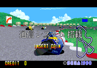
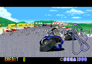
The appearance of an extremely rare game is what. Last Survivor is a game that was mentioned once in a magazine article, was ported a couple of times, and did have an arcade release in Japan. But quite honestly, in the 14 years since I've been working on MAME, we have never, ever seen one come up for sale or auction.
That is, until a couple of weeks ago, when one appeared on a Japanese auction site.
Even more amazing, it was still working! Which is quite the shock since it runs on Sega's X-Board Hardware, and features the evil FD1094 CPU, which contains an encryption key in RAM that is kept alive by a battery. If that battery were to die, the contents of that RAM would be lost forever.
Now, I don't know if the battery is original from 1989 or if it has been since replaced, but either way, getting our hands on a working version of this game was seeming like a more and more remote possibility. But fortunately, someone took good care of this board and we were able to get a clean dump.
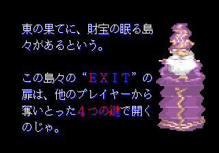
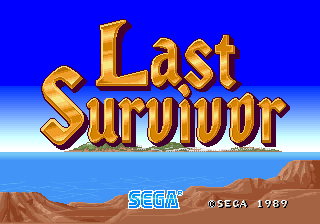
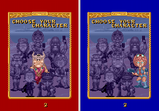
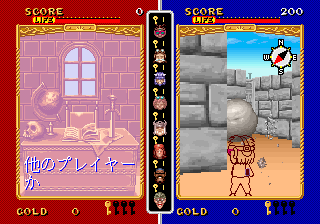
Here are some screenshots:


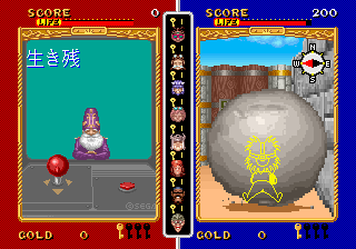
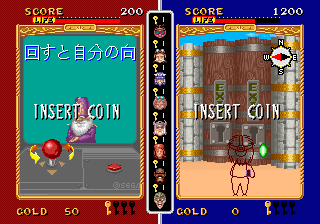
In addition, we also got a dump from the same person of the Japanese version of GP Rider, another X-Board game that still has a working FD1094, thankfully:
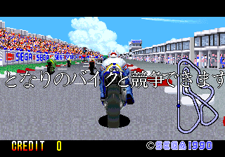
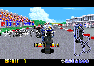
In anticipation of these changes, I've been doing some work to modernize the 16-bit Sega drivers, which have languished a bit since they were so unnecessarily intertwined. Hopefully these changes will all make it in for the next MAME release.
MAME 0.128u4 Changes
A number of people have asked about the changes that went into MAME 0.128u4, and why they were made. This article explains the motivation and reasoning behind these changes, and what still needs to be done.
CPU Context Switching
When MAME was originally designed, it wasn't envisioned that it would eventually be used to emulate multiple CPUs at the same time. MAME 0.1 was derived from Nicola's Multi-Pac emulator, which emulates Pac-Man based hardware, consisting simply of a single Z80 CPU. Eventually, more arcade games were discovered that ran on similar hardware, and a large collection of Z80-based games were quickly supported.
Of course, it was soon discovered that arcade hardware is much more diverse than a single Z80. Support for additional 8-bit CPUs was added, including the 6502 and 6809. In addition, it quickly became apparent that many games had more than one CPU, and so support for multiple CPUs soon followed. There was a problem with running multiple CPUs of the same type, however: the code in the various CPU emulators was not designed to run multiple instances of the same type of CPU at the same time. So in order to make this work, a concept called context switching was introduced.
Let's take the Z80 as our example. The main problem with running more than one Z80 CPU at a time is that the Z80 CPU emulator stored the state of the CPU in global variables. At the time (remember this is back in the days of the 386 and DOS), it was faster to fetch data from global variables than to allocate memory for each Z80 and reference all the CPU state via a pointer.
So in order to allow the Z80 core to continue to work the way it did, we introduced context switching. With context switching, when MAME needs to stop executing one of the Z80's and begin executing one of the others, it asks the first Z80 to copy all of its relevant global variables to some temporary memory, and then copy the second Z80's state from temporary memory back into the global variables. At this point, the global variables contain the state of the second Z80, and it can be executed normally.
In practice, this worked great because MAME would execute the first Z80 for many thousands of cycles, perform a context switch, execute the second Z80 for many thousands of cycles, perform a context switch, etc. In this execution model, the context switch did not require a significant percentage of the total execution time, because it was only done once every few thousand emulated cycles.
Where the problems arise is when we want to do "cycle accurate" execution of these two Z80's. In this case, we really want to run each Z80 for just one or two cycles at a time, and switch back and forth between them many many times per second. When we do this, we execute the first Z80 for a cycle or two, context switch, execute the second Z80 for a cycle or two, switch again, etc. In this situation, it turns out, we spend far more time context switching than we do executing.
The solution to this problem is to get rid of the context switching. To do this, we need to allocate separate memory for each Z80 and instruct each CPU to reference all of its data from that memory, rather than accessing global variables. In the past, doing this was a bit of a performance penalty, but on modern processors and with modern compliers, it is either a wash or marginally faster to do it the "right" way.
Thus, a major motivation behind the changes in MAME 0.128u4 is to make it possible to eventually get rid of the CPU context switching. To do this, the interfaces to all the CPU cores had to change, and each core must be modified to fetch its state from memory pointers instead of global variables. As of the 0.128u4 release, several important CPU cores have been converted, but more work is still pending in this direction.
Memory Context Switching
In addition to the way that CPUs do context switching, the memory system in MAME also does something similar. In MAME, when a CPU needs to read or write to memory, it works with the memory system to figure out whom to call to implement the necessary read/write behavior. Whenever MAME needed to stop executing of one CPU and begin execution of another, it had to perform a memory context switch in addition to the CPU context switch, so that memory accesses from the new CPU accessed the correct memory.
In order to remove memory context switching, the state of the memory subsystem needed to be moved out of global variables and into allocated memory. But it turned out that the memory system wasn't properly organized in this manner, so some significant changes had to be made. In the end, I decided to expose the concept of an "address space" to describe the state of the memory subsystem.
Each CPU can have one or more address spaces, and whenever the CPU needs to talk to the memory system, it hands a pointer to the relevant address space to the memory system so that the memory system knows how to map that memory access. In addition, when the memory system identifies a particular callback in a game driver to handle a read or a write, it also passes along the pointer to the address space structure, so that the game driver has the information it needs to know about handling that memory access.
To make all this work, the interfaces to all the read/write handlers in the system had to change, the memory system had to be rewired, and all of the CPU cores had to be modified to pass along these address space objects. As of 0.128u4, the memory context switch has been removed entirely. Completing this work was a necessary precursor to eliminating the CPU context switching.
The "Active" CPU
One thing that goes hand-in-hand with context switching is the notion of an "active" CPU, which is defined to be the CPU whose context is currently copied into the global variables. As we remove the need for CPU context switching, the notion of an active CPU becomes less well-defined and less meaningful.
Take, for example, a CPU (we'll call it CPU A) which can write to the memory space of another CPU (call it CPU B).
In a context switching system, when CPU A is executing, CPU A's state is loaded into the global variables, and all of CPU A's memory reads and writes use the global memory state information in order to know what happens when memory is accessed. Logically, CPU A is the "active" CPU. Now let's say CPU A performs some action which causes it to modify CPU B's memory space. In order to do this, we must save off CPU A's state (both CPU and memory state), and load up CPU B's state, thus making CPU B the "active" CPU. Then we perform the access to CPU B's memory space. When finished, we save off CPU B's state and restore CPU A's state so that it can continue executing.
In a more modern system, when CPU A is executing, CPU A's state lives off in memory somewhere and can be accessed at any time, and its address spaces are similarly configured so that they can be accessed at any time without context switching. Now CPU A performs the same action which causes it to modify CPU B's memory space. In this case, we don't need to do any context switching. Instead, CPU A can directly modify CPU B's memory space by passing in a pointer to CPU B's address space when it performs its memory operations.
It should be obvious that the big difference in these two scenarios is that there is no context switching in the second case, which should make things faster. But even more importantly, there is no "active" CPU at any point in the second case.
One could argue that because CPU A is executing, that it should be designated "active"; however, even in this case, the notion of active is significantly different than in the first example, because CPU B is never considered active during the transaction. Looking further down the line, it is clear that if we define a CPU as "active" while it is executing, then we forever consign ourselves to only executing a single CPU at a time, because only one CPU can ever be "active" at a time.
Thus, the right solution is to get rid of this "active" CPU notion. Unfortunately, the MAME drivers and core are peppered with references to the active CPU. These must go over time. Only when they are gone can we fully remove the context switching; as long as references to the active CPU still exist, we have to continue to context switch in order to keep up a valid definition of the active CPU.
What Does This All Mean?
For users, all the existing games should continue to work. Speed should be equivalent if not a bit better, especially in situations where there is aggressive context switching today. Once all the context switching is removed, MAME will be doing less work when it switches frequently between different CPUs.
Longer term, however, it is likely that some of these cases will get slower again, because for many early games, the multiple CPUs work closely in concert, and to achieve the most accurate behavior, we ideally should execute each CPU one instruction at a time, alternating back and forth very quickly. Today, this makes performance very bad; with the context switching changes in, I hope it will be bearable at least for many of the 8-bit systems.
For developers, these changes mean that MAME is more object-oriented. Even though MAME is written in straight C and not C++, you can imagine that core structures in the system such as running_machine, device_config, and address_space are objects, and pointers to these objects are passed in and out of most calls in the system. There should be very few if any cases where the need for an "active" CPU is necessary any more, and references to the global Machine (capital "M") object are removed in favor of pointers that are passed into your functions.
The changes we are making aren't particularly revolutionary from a software architecture point of view, but they are revolutionary from a MAME design point of view. There are still many more changes to come as we push toward removing the CPU context switching altogether, but as of MAME 0.128u4 the core infrastructure is in place to make these changes happen. This particular update was the "biggie"; future updates along this path should be smaller until we are in a position to finally remove the CPU context switch for good.
(minor edits on 29-Nov-2008 for clarity)
About Laserdiscs, part 3 (errata)
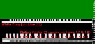
After the last post, I realized that I inadvertantly placed the white flag on line 12, when it is actually on line 11. This caused quite a bit of difficulty as I was trying to get the VBI example picture to line up and it wasn't quite working.
Anyway, I have corrected the article to fix this oversight and provide a brand new VBI example. For this one I have correct line numbers and also overlaid the Philips code binary value on top of the VBI data so it is clearer how it gets extracted.
About Laserdiscs, part 3
As I mentioned previously, laserdiscs directly encode and reproduce the broadcast signal format (either NTSC or PAL). So in order to understand how the information about frame numbers and other details are encoded, it is important to know the basics of the underlying signal format. In this case, I'll talk about NTSC specifically.
An NTSC frame consists of 525 scanlines of data, broadcast 29.97 times per second. As I mentioned before, each frame consists of two fields, which makes each field 262.5 scanlines (yes, it is true that there is an extra half-scanline). Of these 262.5 scanlines, only 240 are normally visible. This is because your classic CRT-based TV set required some time to move the electron beam from the bottom-right of the screen back to the upper-left in preparation for the next field, and 22.5 scanlines' worth of time was decreed to be an appropriate timeframe for this to happen.
These extra 22.5 scanlines each field are known as the Vertical Blanking Interval, or VBI. Traditionally, there is not much of interest transmitted within the VBI area of the field, apart from a few basic control signals that were used for calibrating the picture and synchronizing the timing. Over time, however, people came up with reasons to add useful data to the VBI area. One of the most well-known of these is Closed Captioning, which is encoded on line 21 of each field (the top 22 lines are the VBI, and the following 240 are the visible lines).
Laserdiscs took this a step further, and defined special encodings of their own. Line 11 of each field contains what is known as the "white flag", which is a simple binary indicator of whether the current field is the first field of a frame. Laserdisc players look for this white flag to know how to do a still frame that doesn't consist of a split between two film frames. Since it takes two fields to make one frame, and since many film-based laserdiscs are encoded in a 3:2 cadence, it is not straightforward to ensure this without some additional information.
Even more interesting than the white flag are the "Philips codes" that are encoded on lines 16, 17, and 18 (note that all the laserdisc encodings are on lines different from Closed Captioning, so that laserdiscs could be encoded with Closed Captioning data as well). The Philips codes are special 24-bit digital values that are encoded in the VBI area of each field, and which are used to describe the field. In general, there are up to two Philips codes encoded on three lines, with line 17 generally being a redundant copy of line 18 for added resilience against dropouts or other transmission errors.
So how do you encode a 24-bit binary number into a single scanline of an analog video signal? The answer is to use an encoding technique known as Manchester codes. If you treat bright white as a '1' bit, and black as a '0' bit, then this encoding uses two bits to encode each bit of the code. The reason for two bits is to ensure that the decoded value makes sense, and also to establish a clock for the codes. This works because Manchester codes encode a '0' bit as 10 and a '1' bit as 01. Because of this, you are guaranteed that in the middle of each bit there is a transition from black to white or vice-versa, and this can be used to establish the clock. Once you figure out the clock, then the direction of each transition tells you what the actual value of the bit is.
Below is a picture of the VBI region for a CAV laserdisc. The top few rows are an ugly green because those lines of VBI data were not provided by the capture card. The remaining lines show what the white flag and Manchester-encoded Philips codes look like:
Once the Philips codes are extracted, they can be treated as binary data and evaluated. Unfortunately, it seems as though most of the information about what the various Philips codes mean has been kept relatively secret. However, the most important codes are understood:
| $88FFFF | Lead-in code indicates the field is located before the official start of the disc |
| $80EEEE | Lead-out code indicates the field is located after the official end of the disc |
| $FXXXXX | Frame code specifies the 5-digit frame number (XXXXX) in BCD format |
| $8XXDDD | Chapter code specifies the 2-digit chapter number (XX) in BCD format |
| $82CFFF | Stop code indicates the player should pause at the current field |
So as the player reads data from the disc, it also needs to detect the white flag and Philips codes, and act on them as necessary. By capturing the VBI data along with the normal active video, we are able to preserve this information, and write a laserdisc simulator that operates off of the same information that the original players did.
About Laserdiscs, part 2
All known laserdisc-based videogames use CAV (constant angular velocity) laserdiscs, primarily because these discs could be manipulated in advantageous ways. Players of the era could seek to specific frames, play at different speeds, still frame, play backwards, and perform all sorts of other operations that were not possible with CLV discs.
The reason this was possible is that on a CAV disc, each track corresponds exactly to one frame of video. There are approximately 54,000 tracks on one side of a CAV laserdisc, giving 54,000 frames of video per side. Now, believe it or not, laserdiscs are actually analog devices, meaning that the signal that is stored on them is analog, and is described exactly by the video transmission data standard of its intended country (NTSC or PAL, depending on where you live). Thus, once the data is read from the laserdisc, it is basically identical to the signal that you would receive over the airwaves for watching regular broadcast TV.
Let's step back a moment and think about how laserdiscs of movies work. A movie is traditionally filmed at 24 frames per second. In contrast, the NTSC broadcast standard (which describes how video is transmitted in North America) describes the TV signal as running at 30 frames per second. Furthermore, each frame is built up of two "fields", which are drawn one after another at a slight offset. This is known as interlacing.
Since there are two fields each frame, and the frames run at 30 per second, the result is that the individual fields are transmitted at twice that rate, or 60 times per second (in reality, it is 29.97 frames/second and 59.94 fields/second, but we'll stick to round numbers).
So the question becomes, how do you reproduce a film, running at 24fps, within the NTSC standard, which runs at 30fps (or more precisely, 60 fields/second)? If you transferred one frame of film to one frame (two fields) of NTSC video, the result would play back at 30fps, or 25% too quickly. If you duplicated each film frame onto two frames (four fields) of NTSC video, the result would play back at 15fps, or 38% too slowly.
The solution that engineers came up with many years ago was to realize that 60 / 24 = 2.5. That is, when you look at it in terms of fields instead of frames, each film frame should conver exactly 2.5 fields of NTSC video. However, since you can't split the video midway within a field, they chose instead to alternate between using 3 fields per film frame and 2 fields per film frame. So the first film frame will be duplicated onto the first 3 fields, while the second film frame will be duplicated onto the next 2 fields, and so on. This is known as 3:2 cadence.
The important thing to realize out of all of this is that there was not always a 1:1 relationship between film frames and NTSC frames (though there often was, for example, when the laserdiscs contained video that was originally produced for broadcast TV). That is, if you wanted to view frame #1000 of the actual film, you could not necessarily just seek to NTSC frame #1000 and end up where you wanted. Instead you actually had to go figure out which NTSC frame corresponded to film frame #1000.
When the laserdisc was designed, this discrepancy was actually taken into account. The designers realized that being able to seek to a given NTSC frame was actually not nearly as useful as being able to seek to a particular film frame, and so they devised a way to encode information about the frame numbers on the laserdisc itself.
Which brings us back around to games. For years, laserdisc emulation has relied on "frame files" and "conversion equations" to determine how to map the film frames (which is what all the seek commands target) to NTSC frames (which is what you get when you capture video). But the information about which NTSC frame corresponds to which film frame was present all along in the video signal itself; we were just not aware of it, nor aware of how to capture it.
In the next article, I'll talk about how this information is encoded.